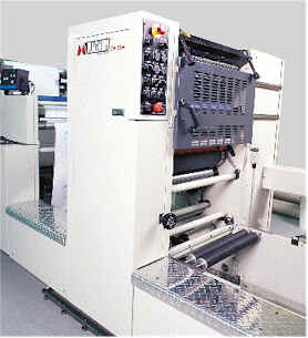
The Magnum ComStar

 .
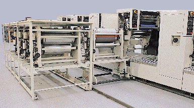
.4 over 4 ComStar press
c/w flexo/varnish unit,double cross-perf and sheeter/rewinder.
For more information, please sign our guestbook.
|
The Magnum ComStar |
|
| .. 4 over 4 ComStar press
c/w flexo/varnish unit,double cross-perf and sheeter/rewinder. |
||
| Magnum ComStar Offset Unit | |||||||||||||||||||||||||||||||||||||||||||||||||||||||||||||||||||||||||||||||||
 General Description General Description A rugged printing unit, the Magnum Comstar offset unit is designed for 3-shift operation. The Comstar print unit is available in widths from 18.5" / 470mm to 26.5" / 620mm. Available circumferences range from 14" / 355mm to 24" / 610mm. A powerful commercial quality inktrain, designed with the aid of a computer will faithfully produce the most demanding print jobs. The standard web path is straight pass eliminating idler rolls in the print units that contact the printed surface. Standard operational features include;
With the variable circumference offset unit circumference changes are accomplished quickly without tools. The cassette change system consists of pneumatically operated lock-up system to clamp and un-clamp the cassettes. Cassettes are also ejected pneumatically onto a rail system. Various interlock systems prevent operation with press running, with cassette out, etc. Spare or extra cassettes can be stored on the optional integrated cassette storage system as shown.
|
|||||||||||||||||||||||||||||||||||||||||||||||||||||||||||||||||||||||||||||||||
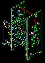
Unit Construction
Print unit side frames are constructed from 1" / 25mm thick steel plate stress relieved and blanchard ground. The side frames are in a "D" type structure where the print cylinder cassette is completely enclosed by print unit framing. Print cylinder cassette side frames are constructed from 1 ½" / 38mm thick steel plate stress relieved and blanchard ground. Side frames are linked by numerous cross ties. A large 1" / 25mm thick steel plate bolted at right angle to the gearside side frame and anchored to the floor adds considerable structural rigidity to the print unit and also functions as the mounting plate for the unit gear box. The resulting frame structure prevents movement in the side frame and effectively dissipates any vibration within the printing unit. A heavy gauge gearside gear enclosure further enhances structural rigidity. This enclosure is lined with a sound deadening material to ensure quiet operation. Unit Geartrain The print unit geartrain is a simple design optimized for torsionally rigidity, superior register performance, reliability and simple maintenance. Drive gears are manufactured from high quality D.I. 65-45-12 a graphite impregnated alloy selected for its sound deadening and long life qualities. Drive gears have a minimum face width of 1 ¼" / 32mm. The main drive gearbox is a rugged spiral bevel unit. The offset unit employs only 9 drive gears with no belts, differentials or chains, yet has full functionality. Fewer gears and a simple design result in more reliable press and easier maintenance. Circumferential register is accomplished by a translating helical gear mounted directly on the unit drive output shaft. 360° unit phasing is achieved by pneumatically disengaging the print cylinders and manually indexing them to the desired position. Differentials used for phasing in other presses tend to be prone to damage, especially in extreme circumstances such as a wrap-up. Differential gearboxes are very expensive to repair/replace. 360° gearboxes are relatively not rigid torsionally and are susceptible to press register problems. The inker is gear driven off the plate cylinder with the result of no backlash through the print cylinders and thereby optimum register performance. A simple and reliable pneumatic gear clutch is used to disengage the print unit. Plate Blanket and Impression Cylinders Print cylinders are constructed from high strength AISI 4140 alloy steel and are hard chrome plated for corrosion and wear resistance. Precision ground and hardened bearers are 1.375" / 35mm wide for long life and optimum print quality. The plate cylinder is mounted in precision double row cylindrical roller bearings. Blanket and impression cylinders are mounted in precision spherical roller bearings. Most print unit circumferences employ "inline stack geometry" optimized for non streaking print. Plate mounting is accomplished by a quick change "snap-in" system which requires no tools and minimizes the non-printing gap. A reel rod plate lock-up system is also available. Blankets are either sticky back or can be mounted with reel rods. Plate blanket and impression cylinders are thrown on and off pneumatically. The impression cylinder to blanket squeeze is fine adjusted by a conveniently located hand wheel. The impression cylinder can be disengaged pneumatically from the press drive for 360° unit phasing. |
| Print Cylinder Dimensions | Inches | mm |
| Plate cylinder circumferences (.025" / 6.35mm increment) | 14 - 24 | 355 - 610 |
| Maximum web width | 18.5 - 26.5 | 470 - 675 |
| Maximum printed width | 18 - 26 | 455 - 660 |
| Plate cylinder undercut | customer | customer |
| Blanket cylinder undercut | customer | customer |
| Plate thickness (std: other available) | 0.006 | 0.152 |
| Blanket thickness -reel rod (std: other available) | 0.65 | 16.5 |
| Blanket thickness -sticky back (std: other available) | .35 | 8.9 |
| Blanket cylinder non printing gap (reel rod blanket) | 0.375 | 9.5 |
| Bearer width | 1.375 | 35 |
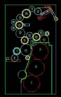
Inktrain Features The design of the inking unit and the roller diameters selected are based on extensive experience and computer aided calculations. Great attention was paid to good accessibility, operational ease and maintenance-free operation. The ink train is designed to rapidly achieve and maintain ink/water balance. The roller diameters are large to minimize ink misting while reducing heat buildup and extending roller life. Sequencing with appropriate delays for the dampener form, ink form rollers and impression is computer controlled minimizes paper waste. The ink fountain roller is driven by ½ hp/.37kw DC motor and is controlled locally from the offset or remotely from the press console. A follower circuit maintains correct ink fountain speed as the press speed changes. A drop down ink fountain facilitates easy clean-up. Other ink train features include;
|
|
| Inker Washup The standard ink wash-up consists of pneumatically operated wash-up pans for each offset unit. An optional auto wash-up system is available.
Dampening System Dampening is accomplished with a 3 roll continuous dampening system. The transfer roller has a highly polished hard chrome finish to enhance wetting properties especially when running with alcohol substitutes. A copper underlay is present under the chrome cover for superior corrosion resistance. The system is driven by ¼ hp/.19kw DC motor and controlled locally from the offset or remotely from the press console. A follower circuit maintains correct dampening speed as the press speed changes. A low water level sensor in the water tray will shut down the press to protect the metering roll in case of no water. A central dampening solution circulating system is supplied, a chiller is optional. Available Options
|
||||||||||||||||||||||||||||||||||||
|